86 4006-636-096
|
|
|
▶ Waveguide Straight Sections ▶ Waveguide Bends ▶ Waveguide Transitions ▶ Flexible Seamless Waveguide ▶ Flexible Twistable Waveguide ▶ Waveguide-Coaxial Adapters ▶ Waveguide Loads ▶ Waveguide Gaskets ▶ Waveguide Shorts ▶ Waveguide Pressure Windows |
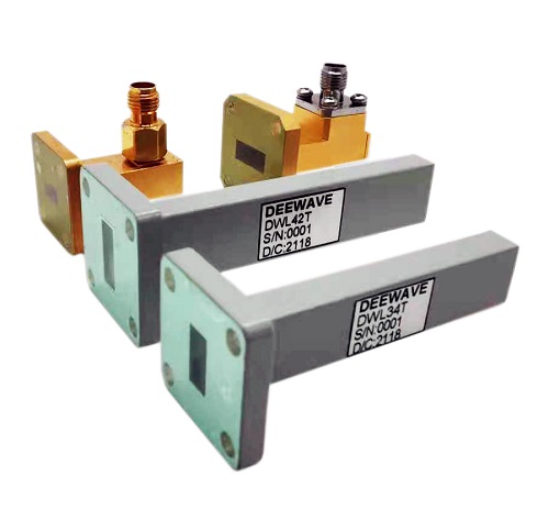
DEEWAVE Electronics supply a variety of waveguide components, such as waveguide connectors, waveguide adapters, waveguide loads, and etc. And waveguide type information as below
|
Waveguide Type |
Frequency Band Name |
Recommended Frequency Band |
Inner Dimensions of Waveguide Opening |
|
|
(Inch) |
(mm) |
|||
|
WR650 |
L Band (part) |
1.15 — 1.72 |
6.500 × 3.250 |
165.1 × 82.55 |
|
WR510 |
— |
1.45 — 2.20 |
5.100 × 2.550 |
129.5 × 64.77 |
|
WR430 |
— |
1.72 — 2.60 |
4.300 × 2.150 |
109.2 × 54.61 |
|
WR340 |
S Band (part) |
2.20 — 3.30 |
3.400 × 1.700 |
86.36 × 43.18 |
|
WR284 |
S Band (part) |
2.60 — 3.95 |
2.840 × 1.340 |
72.14 × 34.04 |
|
WR229 |
C Band (part) |
3.30 — 4.90 |
2.290 × 1.145 |
58.17 × 29.08 |
|
WR187 |
C Band (part) |
3.95 — 5.85 |
1.872 × 0.872 |
47.55 × 22.2 |
|
WR159 |
C Band (part) |
4.90 — 7.05 |
1.590 × 0.795 |
40.38 × 20.2 |
|
WR137 |
C Band (part) |
5.85 — 8.20 |
1.372 × 0.622 |
34.90 × 15.8 |
|
WR112 |
— |
7.05 — 10.00 |
1.122 × 0.497 |
28.50 × 12.6 |
|
WR90 |
X Bband |
8.20 — 12.40 |
0.900 × 0.400 |
22.9 × 10.2 |
|
WR75 |
— |
10.00 — 15.00 |
0.750 × 0.375 |
19.1 × 9.53 |
|
WR62 |
Ku Band |
12.40 — 18.00 |
0.622 × 0.311 |
15.8 × 7.90 |
|
WR51 |
— |
15.00 — 22.00 |
0.510 × 0.255 |
13.0 × 6.48 |
|
WR42 |
K Band |
18.00 — 26.50 |
0.420 × 0.170 |
10.7 × 4.32 |
|
WR34 |
— |
22.00 — 33.00 |
0.340 × 0.170 |
8.64 × 4.32 |
|
WR28 |
Ka Band |
26.50 — 40.00 |
0.280 × 0.140 |
7.11 × 3.56 |
|
WR22 |
Q Band |
33.00 — 50.00 |
0.224 × 0.112 |
5.68 × 2.84 |
|
WR19 |
U Band |
40.00 — 60.00 |
0.188 × 0.094 |
4.78 × 2.39 |
|
WR15 |
V Band |
50.00 — 75.00 |
0.148 × 0.074 |
3.76 × 1.88 |
In the microwave region of the electromagnetic spectrum, a waveguide normally consists of a hollow metallic conductor. These waveguides can take the form of single conductors with or without a dielectric coating. Hollow waveguides must be one-half wavelength or more in diameter in order to support one or more transverse wave modes.
Waveguides may be filled with pressurized gas to inhibit arcing and prevent multifactor, allowing higher power transmission.
Waveguides are almost exclusively made of metal and mostly rigid structures. There are certain types of "corrugated" waveguides that have the ability to flex and bend but only used where essential since they degrade propagation properties. Due to propagation of energy in mostly air or space within the waveguide, it is one of the lowest loss transmission line types and highly preferred for high frequency applications where most other types of transmission structures introduce large losses. Due to the skin effect at high frequencies, electric current along the walls penetrates typically only a few micrometers into the metal of the inner surface. Since this is where most of the resistive loss occurs, it is important that the conductivity of interior surface be kept as high as possible. For this reason, most waveguide interior surfaces are plated with copper, silver, or gold.
Voltage standing wave ratio (VSWR) measurements may be taken to ensure that a waveguide is contiguous and has no leaks or sharp bends. If such bends or holes in the waveguide surface are present, this may diminish the performance of both transmitter and receiver equipment connected at either end.